ОРИГИНАЛ СТАТЬИ ФИРМЫ "GARRETT"
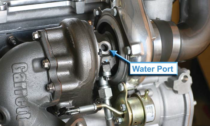
Water ports are located on either side of the turbo’s center housing. Water should flow through the center
housing from right to left, or left to right. If there are more than two ports to choose from, be sure to use
one on either side of the center housing (don’t plumb both lines in on the same side).
White Paper No. 1
Water-Cooled Turbochargers: They Need Water!
“Does my turbo really need water? Is it really that thirsty? What gives? Why should I care?”
The Garrett® engineers are asked many such questions regarding our water-cooled turbochargers.
Many customers question the necessity or benefi ts of plumbing in those extra water
lines to the sides of the turbo’s center housing. Why not just leave them off? The reality is that
a water-cooled turbo can be damaged irreparably without proper water line setup. With a little
background and some explanation of what water cooling really does for turbochargers, this
Garrett® white paper will hopefully convince a skeptic that the benefi ts provided by water-cooling
are worth the small effort required to properly set it up.
What does water-cooling really do?
Water-cooling improves mechanical durability and lengthens the turbocharger’s life. Many
turbochargers are designed without water cooling ports and are suffi ciently cooled by air and
the lubricating oil that fl ows through them. Other turbochargers, such as many in the Garrett®
GT & GTX ball bearing lineup, are designed from the beginning to be cooled by oil and water.
How can we tell the difference between an air/oil-cooled turbo and an oil/water-cooled turbo?
If the turbocharger’s center housing has threaded ports on either side, at 90° from the oil inlet/
outlet fl anges, then it is water-cooled. In order to meet durability targets defi ned by Garrett®
engineers during its development, it needs water fl owing through it.
Water cooling’s main benefi t actually occurs after the engine has been shut down. Heat
stored in the turbine housing and exhaust manifold “soaks back” into the center section of
the turbocharger after shutdown. If water is not plumbed correctly, this intense heat can
potentially destroy the bearing system and the oil-sealing piston ring behind the turbine
wheel.
How does water-cooling work?
The physical process of turbocharger water-cooling is an interesting one, and works in
a different way than what might seem obvious. It is true that during normal engine operation water
flows through the turbocharger mostly due to pressure created by the engine’s
water pump. However, an additional phenomenon known as “thermal siphoning” pulls water
through the turbo’s center housing if the water lines are properly routed, even after the engine is
shut off and the water pump is no longer pumping.
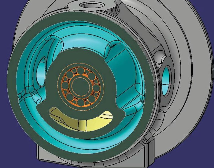
Turbo center housing shown in cutaway view, with water cavity (blue), oil cavity (yellow).
Water cavity completely surrounds ball bearing cartridge (orange) and has a port on either side for water inlet & outlet.
Heat in the center housing is transferred to the water via conduction, like the cooling effect
that occurs inside a typical water-cooled engine (with a water jacket surrounding each
cylinder and running through the cylinder head). If the water running through a turbocharger
is allowed to escape freely after absorbing heat, it will rise through the cooling system pulling
cooler water into the turbocharger along with it. In this way the intense heat that has soaked
back into the turbo after engine shutdown is wicked away from the bearings and seals, and
prevented from causing serious damage without assistance from the engine’s water pump.
How does water-cooling extend turbo life?
“Heat soakback” is a major turbo killer and must be taken seriously by turbocharger engineers
and turbo users alike. This damaging heat originates in the exhaust system. During
hard usage, high exhaust gas temperatures dump massive amounts of heat into the exhaust
manifold, turbine housing, and turbine wheel. These components are designed to handle
very high temperatures through careful design and materials selection. However, some of
this stored heat will want to naturally make its way into the less-heat-tolerant center housing,
bearing system and shaft of the turbocharger through conduction, since these components
are all in contact with one another. While the engine is running and oil is fl owing through the
turbo’s bearing system, most of the transferred heat will be absorbed by the oil, preventing
damage to the bearings and oil seals. Once the engine is shut down, the oil fl ow stops and
so does the exhaust gas fl ow through the turbine – but all of that heat stored by the exhaust
manifold and turbine housing still remains. This heat must go somewhere. Its only escape
paths are either to be transferred via conduction into the turbo’s center section and the exhaust
downpipe, or to radiate into the surrounding air under the hood. A small amount of heat
will be transferred to the surrounding air via radiation and convection, but the great majority
will conduct from the turbine housing into the center housing, since the center housing is at
a lower temperature. Additionally, some of the heat will travel from the turbine wheel into the
shaft and out towards the bearing system.
During this phase of turbine & exhaust cool down, as the heat is “soaking back” into the
turbo’s center section, the temperatures of the center housing, oil seal, bearings and any oil
remaining in the turbo are all elevated above the normal operating temperatures that occurred
while the engine was running, since the oil fl ow is no longer available to carry heat away. This
effect is worsened by a large turbine housing. The larger the turbine A/R (and/or the more
massive the turbine housing) the more heat is stored in the housing during operation. Therefore
there is a greater risk for damage to the turbo during heat soakback after shutdown.
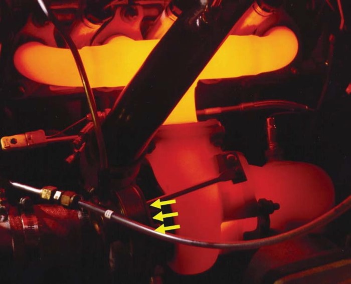
Intense heat in the exhaust manifold and center housing will remain once engine is shut down, and travel into the turbocharger’s
center housing (in direction of yellow arrows) where it can wreak havoc on the bearing and seals.
How can a turbo be damaged by insufficient cooling?
Now that we have seen how turbo water-cooling works and what it is up against, we can
begin to understand the consequences of insuffi cient cooling. Both the bearing systems and
the oil sealing systems can be damaged by being overheated. Ball bearing cartridges are
very robust and stand up to repeated abuse, but there are limits to the extremes that they can
survive. Ball bearing cartridges are composed of a set of inner races, two sets of balls and retainers,
and an outer race. Both the inner and outer races are made of various grades of steel
that are very strong and hard under normal operating conditions, but which are reduced when
temperatures get too high. The strength and hardness of a typical ball bearing race starts to
rapidly degrade at temperatures above 300°F (150°C). This may seem low considering that
exhaust gas temperatures can get as high as 1800°F (980°C) in a typical high-output turbocharged
gasoline engine, but the bearing is heavily protected by several lines of defense: a
heat shroud behind the turbine wheel, reduced contact area between the center housing and
the turbine housing (reducing heat transfer rates), oil & water cooling during operation, and
finally, water-cooling after hot shutdowns.
Examining water-cooling specifi cally, the water jacket inside the turbocharger’s center
housing wraps around the ball bearing cartridge and is designed to keep ball bearing temperatures
below the limits to prevent bearing failure. When water is not used or not plumbed
correctly, bearing temperatures can easily go over the intended limits and result in increased
bearing play, turbine and compressor wheels rubbing in their respective housings, and ultimately
catastrophic turbo failure. In addition to this material degradation, high bearing temperatures
cause the internal clearances to decrease in a steel ball bearing cartridge. If temperatures
get too high and the turbocharger is run at higher than rated turbo speeds, a steel
ball bearing cartridge can physically lock up or seize, causing catastrophic turbo failure.
High speeds occur hand-in-hand with very high boost pressures, so turbo users running a
high-boost system should be extremely conscious of the setup and condition of the turbo’s
water-cooling lines. “High boost” varies from turbo to turbo, but can generally be considered
anything above 25psig (1.7 bar).
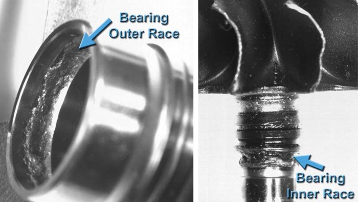
Ball bearing races damaged by intense heat and high turbo speeds. The ball bearings
had a tough time rolling over these surfaces!
Each individual ball bearing inside the Garrett® dual ball bearing cartridge is held in place
by a retainer, and there is one retainer per set of balls: one on the compressor side of the
turbo and one on the turbine side. Elevated temperatures can also damage these retainers,
which can lead to severe shaft motion (or play), wheels rubbing in housings, and again
– catastrophic turbo failure. Keep your bearing retainers happy – don’t over-cook them!
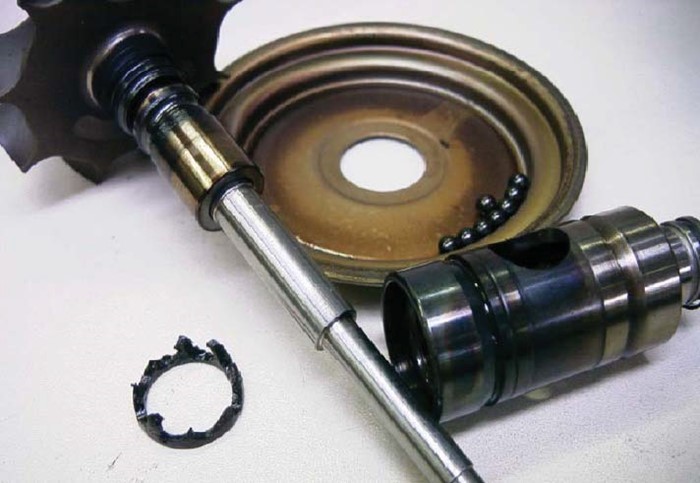
Overheated ball bearing cartridge, disassembled showing damaged retainer at lower left. Bearing races are blued and damaged as well.
Excessive play is the result of retainer and race damage, often culminating in wheel to- housing rubbing and total turbo failure.
Insuffi cient cooling and very high temperatures not only risk the health of the bearing
system; they can potentially destroy the oil seals as well. When oil is overheated, it will oxidize
and produce “coke,” a solid carbon-based residue that appears as a black caked-on sooty
substance. Turbocharger oil seals are not conventional rubber shaft seals like on an engine’s
crankshaft because rubber seals or o-rings would not be able to maintain their sealing
properties at the high temperatures inside turbochargers. Instead, they are steel “piston rings”
that ride in grooves in the turbo shaft. They are springy and designed to press against a bore
in the center housing, just like piston rings in an engine cylinder. They also need to have some
freedom of motion to work properly – a small amount of axial movement is necessary (in &
out, in the direction of the shaft). If overheated oil turns to coke in the seal area, the piston
ring seal groove can be fi lled with coke and will over-constrain the ring. This can lead to the
ring rubbing on the shaft, which it should not do. This constraint of free motion coupled with
overheating will cause the ring to deform plastically as it expands outwards into the seal bore
in the center housing. The plastic (irreversible) deformation is known as ring collapse, and
once the turbocharger cools down the piston ring seal has lost its springiness and cannot
function as an oil seal any longer. In this way, the lack of functional water cooling can cause
severe oil leakage from the center housing into the turbine housing, which will generate
smoke as the oil is burned by the hot exhaust gasses.
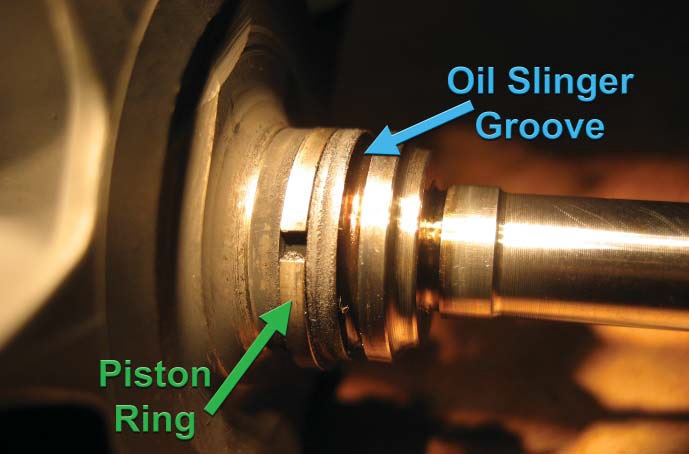
Oil-sealing piston ring with gap visible, facing camera. Turbine wheel is at left, shaft is at right. These parts
are used but in good condition – they have not been overheated and no coked oil is visible.
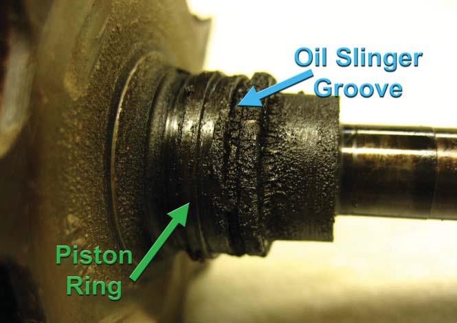
Similar turbine wheel & shaft assembly, but this one has been repeatedly overheated. Piston ring groove and oil slinger groove both contain coke.
If this piston ring has not yet collapsed, it is only a matter of time before it does. Severe bluing (discoloration) of the
steel shaft on right is also visible, indicating the turbocharger has not been properly cooled or has operated above the maximum rated temperatures.
What is the right way to set up a water-cooled turbocharger?
The damaging effects of heat soakback can be prevented from destroying the turbocharger
through proper installation of the water lines in the cooling system. Water-cooling
a turbocharger does not need to be a complex project. The turbo’s water lines should be
plumbed into the engine’s existing cooling system, and can be teed off of the heater lines if
they are still present in the vehicle and convenient. Engine coolant (antifreeze) can be used
without worry – water-cooled Garrett® turbochargers are qualifi ed during heat soak-back
testing using a typical 50/50 mixture of water and antifreeze, at a temperature of 196°F
(91°C). In order to get the greatest benefi t from water-cooling, the turbocharger’s center
housing should be rotated around the central axis (the shaft) so that the water ports are at
an angle of approximately 20° from the horizontal. This is necessary to promote the thermal
siphoning effect discussed earlier. The input water (colder side, from the engine’s cooling
system) should be plumbed in to the lower of the two ports after the housing is rotated. The
hotter output water leading back into the engine’s cooling system should be plumbed into
the higher port and allowed to travel “uphill” all the way back to where it meets the cooling
system. No up/down kinks or “traps” should be present in this return line. Either side of the
turbocharger can be used as the outlet – the water core was designed for fl ow in either direction.
Proper plumbing execution in this way, with the colder water entering from the low
side, leading into the rotated center housing and exiting the higher side, will reduce formation
of air pockets and allow unrestricted fl ow during the thermal siphoning period after the
engine is shut down. Full benefi t of the thermal siphoning effect will be realized and internal
turbo temperatures will be minimized. Garrett® laboratory testing has shown that peak temperatures
in the center housing can be reduced by as much as 90°F (50°C) when the center
housing is rotated to allow the hotter outlet water to escape from the higher port. Rotating
the housing more than 20° from horizontal may further reduce temperatures slightly but may
also impede oil drainage, so stick with 20° as a maximum.
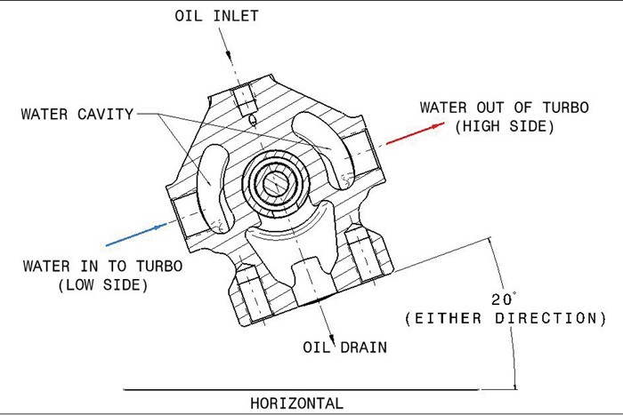
Cross-section view of center housing, showing bearing cartridge in center, oil inlet & drain, and water ports on either side. Center housing should be
rotated to 20° from horizontal in either direction to promote efficient thermal siphoning.
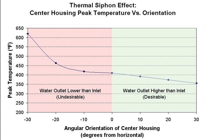
Graph showing center housing peak temperature vs. center housing orientation, as measured during heat soakback testing.
Green zone to right shows lower temperatures resulting from proper water line setup, with outlet port higher than inlet. Red zone to left
shows dramatic temperature increase as housing is rotated in the “wrong” direction, with the water outlet port lower than the inlet.
A great deal of different types of water lines can be used with success, but there are several
guidelines to follow when selecting the lines. Be sure to use hoses or lines that are rated to at
least as hot as the engine coolant temps will ever get, which can be as high as 250°F (121°C)
or higher in some cases. The lines or hoses should be designed to be compatible with water
and antifreeze, and most are. AN-style (37° fl are) fi ttings are recommended for easy installation
and leak-free systems, and a variety of adapters to Garrett® water ports are available from
many distributors. Either hard steel lines or fl exible lines can be used, but care must be taken
to ensure hard lines are not subject to damaging vibration. As the engine is running there will
be normal engine vibration, but there will also be movement of the lines as the engine rotates
on its mounts during high torque output. Hard lines without some sort of fl exible section between
their ends can be cracked or bent from engine rotation or fatigued from normal engine
vibration, depending on how they are routed. Cracked hard lines will lead to coolant leaks, so
extra consideration for motion and vibration should be taken when using hard lines.
Most automobile engines are water-cooled, meaning that plumbing in a water-cooled turbocharger
should be fairly straightforward. Air-cooled engines exist in performance vehicles
though and can cause some extra work for those who run them in conjunction with a watercooled
turbocharger. Ideally a separate water-cooling system should be constructed, with a
reservoir tank, small radiator, and possibly an electric water pump. If the thermal siphoning effect
is given priority when laying out the lines and reservoir placement, a water pump may not
be necessary since the heat inside the turbocharger will naturally work to circulate the cooling
water through the system. If in doubt, closely monitoring coolant temperatures with gauges
and/or data logging is strongly recommended to ensure that the system is adequate and the
turbocharger is supplied with water or coolant at a temperature below approximately 250°F
(121°C) on the input side. Vehicles with extremely low exhaust gas temperatures and no water
cooling system (low-output diesels or purpose-built methanol / alcohol fueled dragsters, for
example) may not require a water-cooling system for the turbocharger. In this case the condition
of all turbo components should be closely monitored to ensure the bearings remain in
good condition and oil coke is not forming. If in doubt, set up a simple water cooling system.
In summary, water-cooling is an important and fairly straightforward requirement for turbochargers
that are equipped with water ports. The consequences for overheating a watercooled
turbocharger can be intensely destructive, and the reward for a thoughtfully laid-out
water-cooling system in good working order is a turbocharger that will be allowed to live the
longest life possible under the extremely demanding conditions that it must endure. By making
a modest effort to plumb water lines to your turbo, you are giving it a fi ghting chance at survival
in your high performance vehicle.
Water Cooling Installation Checklist.
1. Rotate (clock) the center housing to 20° from horizontal, either direction, once turbo
is installed
2. Choose suitable locations to tap the vehicle cooling system. The turbo can be
plumbed in-line with a heater line or heater hose if convenient.
3. Ensure water will always fl ow through turbo regardless of whether heater valve is
open or closed
4. Check www.turbobygarrett.com or the Garrett® catalog to fi nd the water port thread
specifi cations for your particular turbo
5. Choose lines and adapters based on the port threads and desired layout in the
vehicle
6. Plumb the colder (input) water into the lower port on the center housing
7. Run the hotter (output) water from the higher port on the center housing
8. Ensure there are no up/down undulations in the output line leading back to cooling
system
9. If hard lines are used anywhere in the system, use fl exible sections to prevent
cracking due to vibration or engine torque
10. Use crush washers to seal connection to center housing water ports
11. When refi lling cooling system after turbo installation, check coolant level frequently
and top off as needed
12. Be sure that cooling system is completely bled, with no air pockets remaining
13. If engine is air-cooled, carefully consider a separate water cooling system when
using a water-cooled turbocharger.